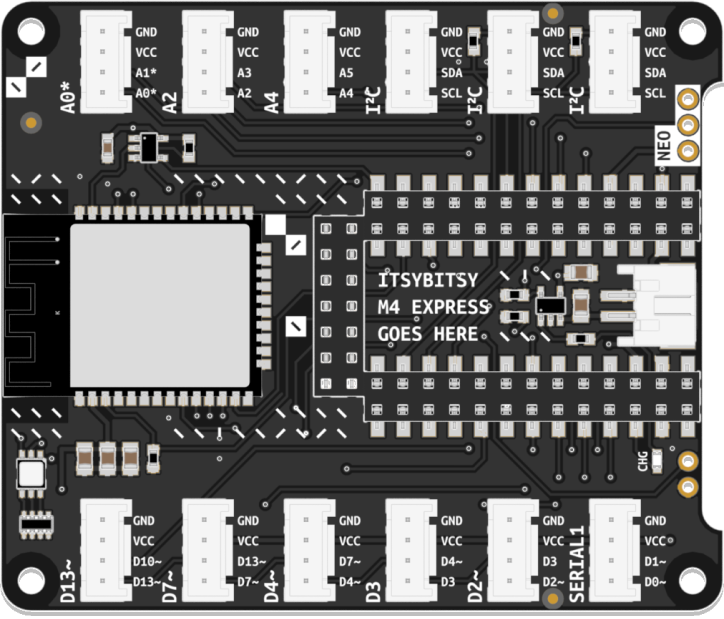
Bitsy Expander M4
Expands the capabilities of your microcontroller. Provides solderless connectors, WiFi connectivity, battery management, and more.
Features
- 12 Grove Headers
- 5 Digital Headers with overlapping (shingled) pins: D2, D3, D4, D7, D13
- 1 Digital Header with exclusive pins: SERIAL1
- 3 Analog Headers with exclusive pins: A0, A2, A4
- 3 I²C Headers
- ESP32-WROOM Co-Processor for WiFi and BLE
- 1 JST PH 2-pin connector for 3.7V LiPo Batteries (chargeable via ItsyBitsy’s USB port)
- 1 Logic-shifted output (allows driving components requiring 5V logic while powered via USB)
NOTE: In shingled pin headers, each header’s second pin is shared with the first pin in the header above it. Therefore, using one disables the other. For instance, using pins D3 and D4 in the D3-labeled header disallows the use of D4 in the D4-labeled header.
Usage Information
You will be introduced to the usage of the Bitsy Expander in the course of the tutorials. The information below serves for reference. If you are interested in additional information on the capabilities of your expander board, visit the documentation on its GitHub repository.
WiFi and BLE
The Bitsy Expander uses an ESP32 WROOM module to provide WiFi and Bluetooth Low Energy (BLE) functionality to the ItsyBitsy.
The ESP32 module is connected as follows:
| ESP32 Pin | ItsyBitsy Pin |
|---|---|
| Chip Select (CS) | D9 |
| Busy (BSY) | D11 |
| Reset (RST) | D12 |
| SPI Clock (SCK) | SCK |
| SPI MISO | MISO |
| SPI MOSI | MOSI |
Battery Charging
The default battery charging current is 100mA. A faster, 500mA charging mode is available for batteries that support it. It can be enabled by closing the solder jumper.